 Antron
99,rohn towers,tower,cb.cb radio,ham,ham radio,27.175,tennessee,shotgun county,how to build a tower,d 104,galaxy,moonraker 4
Antron
99,rohn towers,tower,cb.cb radio,ham,ham radio,27.175,tennessee,shotgun county,how to build a tower,d 104,galaxy,moonraker 4
My First CB Radio Tower.
By:
Thanks to Cookieman Number 1 Station in the Nation, Doublenickle & Daydreamer
Click here for: Aliens Kidnapped Cookieman
Click here for: Mr. Wanna B. Possum
Antron
99,rohn towers,tower,cb.cb radio,ham,ham radio,27.175,tennessee,shotgun county,how to build a tower,d 104,galaxy,moonraker 4
Greetings and Welcome
Below you will find the beginnings of building a 12" Rohn Tower for my CB Radio Hobby. With little or no experience I acquired a used Rohn Tower from a couple of local CB'ers. Okay I have the tower now what? Can I do this? Do I need to hire a contractor? Please understand that everything you read here is simply my onion or understanding. This is how I did things. This doesn't make it right or wrong. Please enjoy and I hope that this will give someone insight and help to avoid some complications in the building of a tower.
This page is slow loading if accessed with dialup.
Get Coffee Now!
Click on photos to enlarge view.
After the photos fully load you can hold your mouse on the lower right hand corners of the photos to enlarge them by clicking on the X.
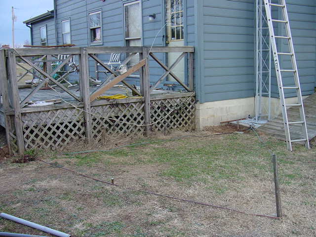
Planning the Tower.

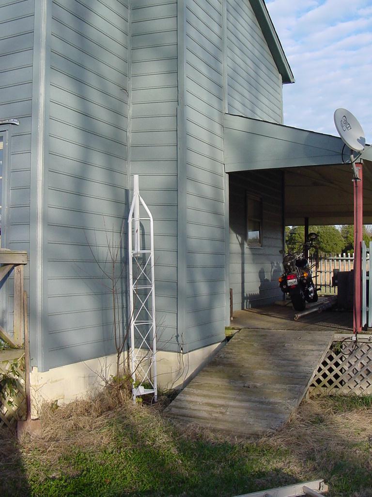
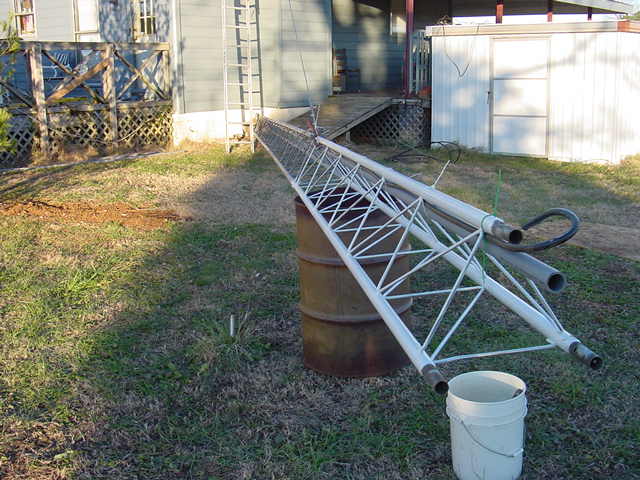
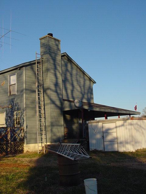
Set Rohn tower in place on partial baseplate. Tree removal was necessary. Everything looks as if it will work here.
Okay here we go.
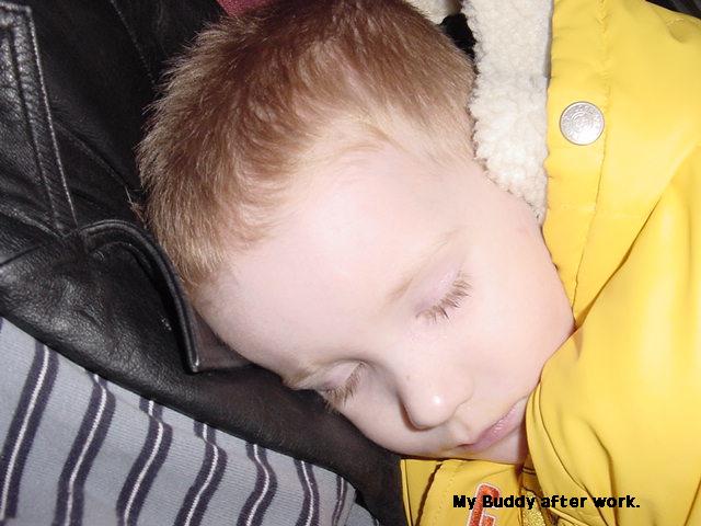
Warning: Never attempt to build your first tower without a Buddy to help. A must for all tower building projects.
Attached to existing foundation. Dug approximately 18" deep. Knocked two holes thru blocks and inserted 1/2" rebar with bends into blocks and to bottom of concrete.
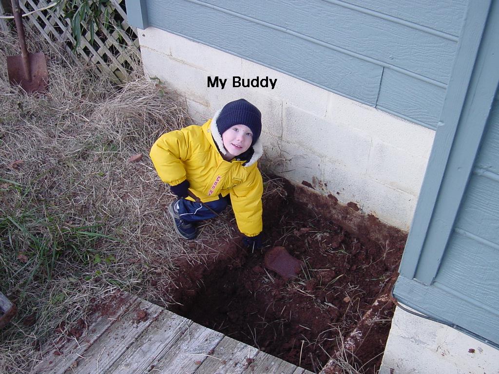
My Buddy
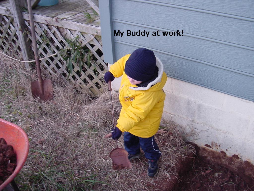
My Buddy At Work
Baseplate
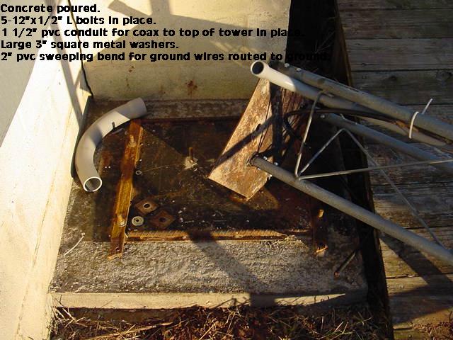
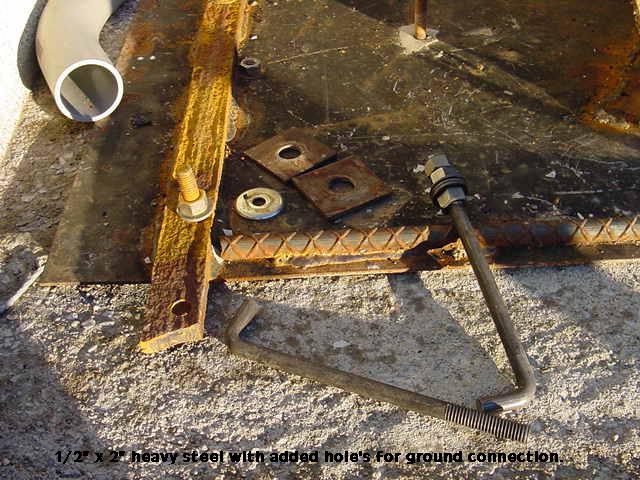
If I had it to do over Id get all 1/4" steel material at minimum. I had this piece of 1/8" plate laying around and decided to make use of it by adding the 1/2" x 2" steel and 1/2" rebar to strengthen it for the bottom of hinged base plate. Five 12" steel L bolts were used. One of which goes thru the folding hinge plate. Notice the additional holes left to connect ground wires to base plate.
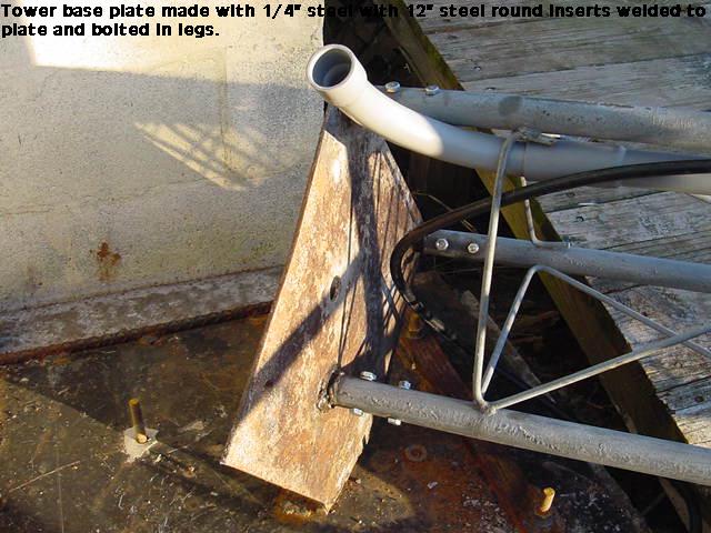
All legs are bolted with two steel bolts per leg.
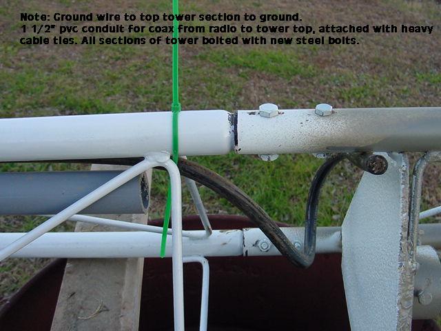
1 1/2" pvc attached to tower leg to top of tower for coax & rotor wiring. This is not necessary but decided to add the protection for the best coax I could find.
Note: PVC and top tower ground wire attached to back tower leg for ease of climbing tower if necessary.
Wire ties left uncut for clarity in photo.
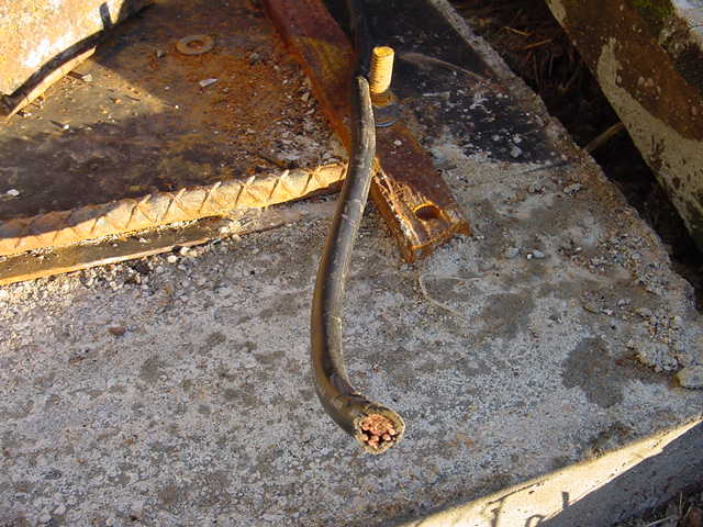
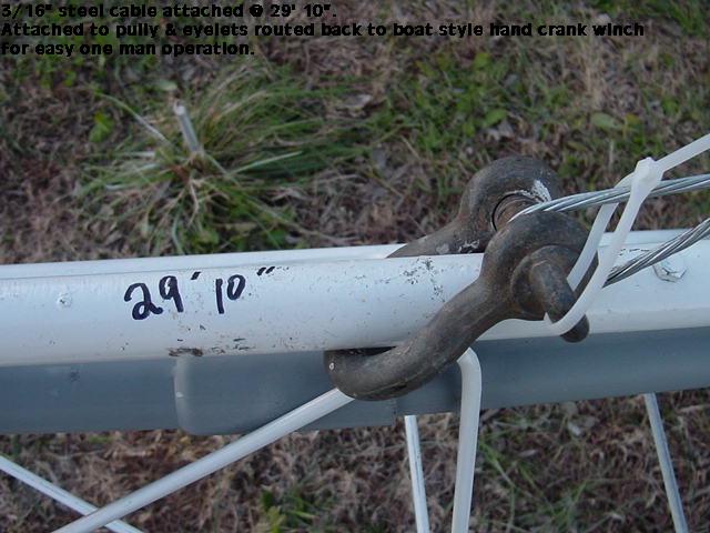
In this photo you should notice the 3/16" steel guy attached for the hand crank winch. The top tower portion is left unattached at this point. It is easy to see the PVC on the back leg along with the ground wire to top portion. My first Antron 99 was grounded to one ground rod and took a direct lightening strike and exploded along with a few thousand dollars worth of other phones, printers, radios, etc. After much research the grounding system that will be attached to this tower should greatly eliminate the chances of this happening again.
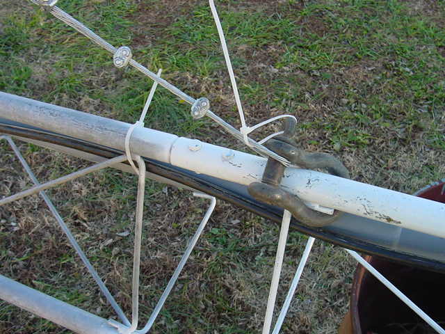
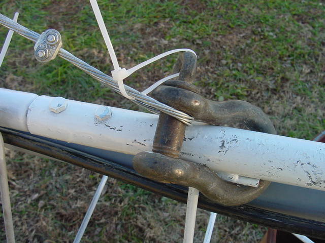
A very heavy clevis was used here to attach 3/16" steel raising guy with three galvanized clamps on wire. A wire tie was added to help insure clevis to remain intact. All bolts and connections from top to bottom should be inspected every time the tower is lowered.
1/4" steel bracket is attached to two tower legs at the highest point on building. You can see the bolt holes that also have a steel bushing that attach the tower to the building.
One man hoist operation.
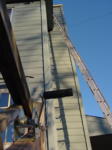
This photo reveals the 3/16" steel raising guy. Notice the guy wire at the top of the ladder. This point is where an eye bolt goes thru the wall of the house. Extra framing was required here to insure the necessary support. The hand crank was acquired at the local Tractor Supply. It was rated for something like 2300 pounds. Steel eyelets were added in approx. 4 places to guide the guy wire for alignment purposes. Additional 4x4's were added to existing deck for the crank. Large nails and lag bolts were used. Never underestimate the weight and pull here. Additional pressure treated 2x4's were added at the top of the chimney to keep the tower off the house and to match the tower to leg brace to be attached here. Nailed and lag screwed also.

Here you can see the eyelets for simple cable guidance.
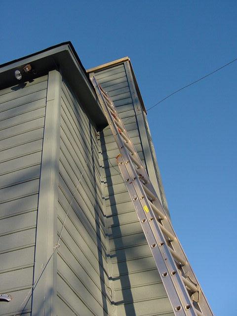
Pulley attached behind top of ladder to beefed up area thru the wall. Also this pulley should be rated far above weight of tower. Notice the eyelet to guide wire towards crank.
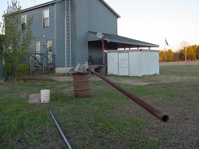
This photo shows where the tower will lay up in place and attach at the top of chimney. The tower will be approx. 3-4 inches from the chimney. First tower support will be at the top of chimney. This leaves approx. 20' above the chimney that will have to be guyed later. Top section of tower is not installed yet.
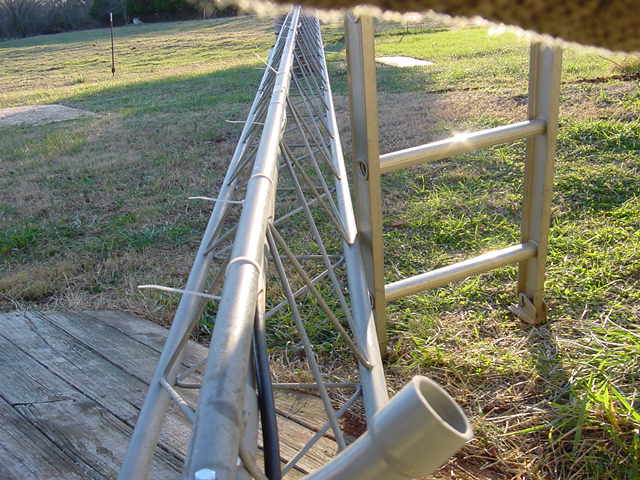
Rohn 12" Tower

Looking down the 12" Rohn Tower legs you will see the z bar bracing and the coax pvc, the top ground wire. This wire will directly attach ground to the top section of tower which antenna mast is attached too. This ground wire is exceptionally large for the purpose. Just happened across it and opted to use it. Donated for the cause.
This is the other end of top tower ground wire mentioned above. It will attach to the hole in 1/2" x 2" steel which will attach to 1/2" copper water pipe flattened bolted and soldered at this point.
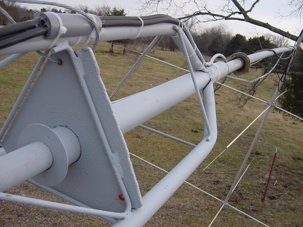
Top Tower Section
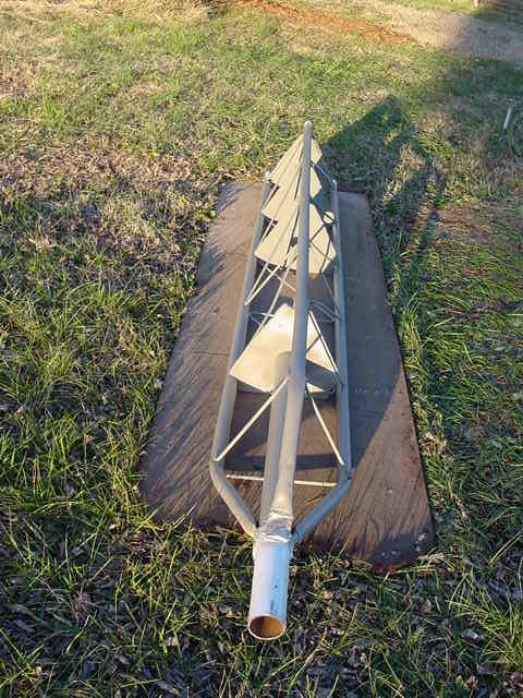
Top section of tower. Primed and fabricated for mast pole. Top 2" tube will fill with grease to aid the small Radio Shack $79.00 rotor. If this last a couple years I figure I'm ahead of the $$ game. If not Ill let you know.
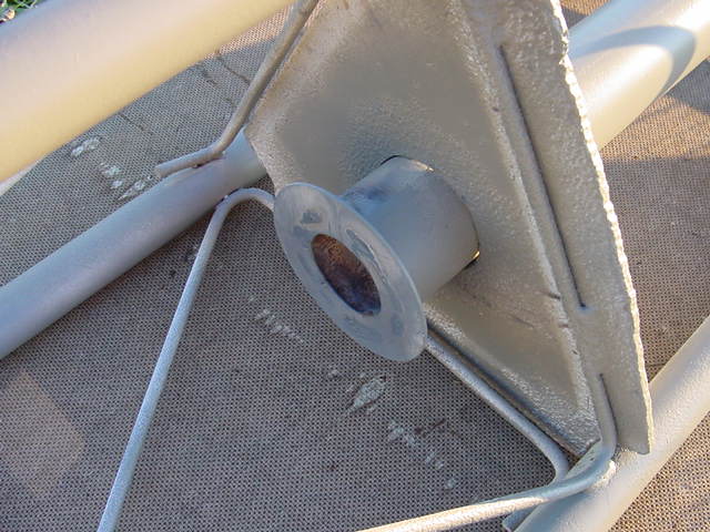
Steel sleeve added with friction fit for 1 5/8" od pipe. This tube holds the grease along with fitting up approx. halfway.
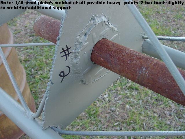
Notice the welds to z braces on 1/4" steel plates underneath.
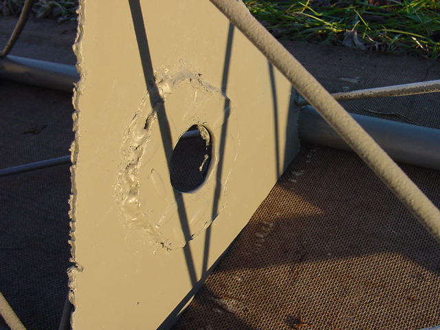
The second 1/4" steel plate with another 1/4" steel friction fit sleeve welded for 1 5/8" od pipe where mast comes down thru to meet with rotor. I didn't go to the trouble of cleaning up cuts on 1/4 steel plates. Looks to me are not that important with good primer and paint that protect the tower in the long run. Its hard to see this imperfection at 40-50 '.
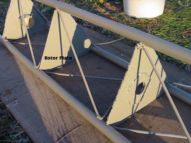
Rotor sits below last plate discussed. Holes are not drilled yet. Mast pipe will run wild for cut off to match rotor.
Ditto!
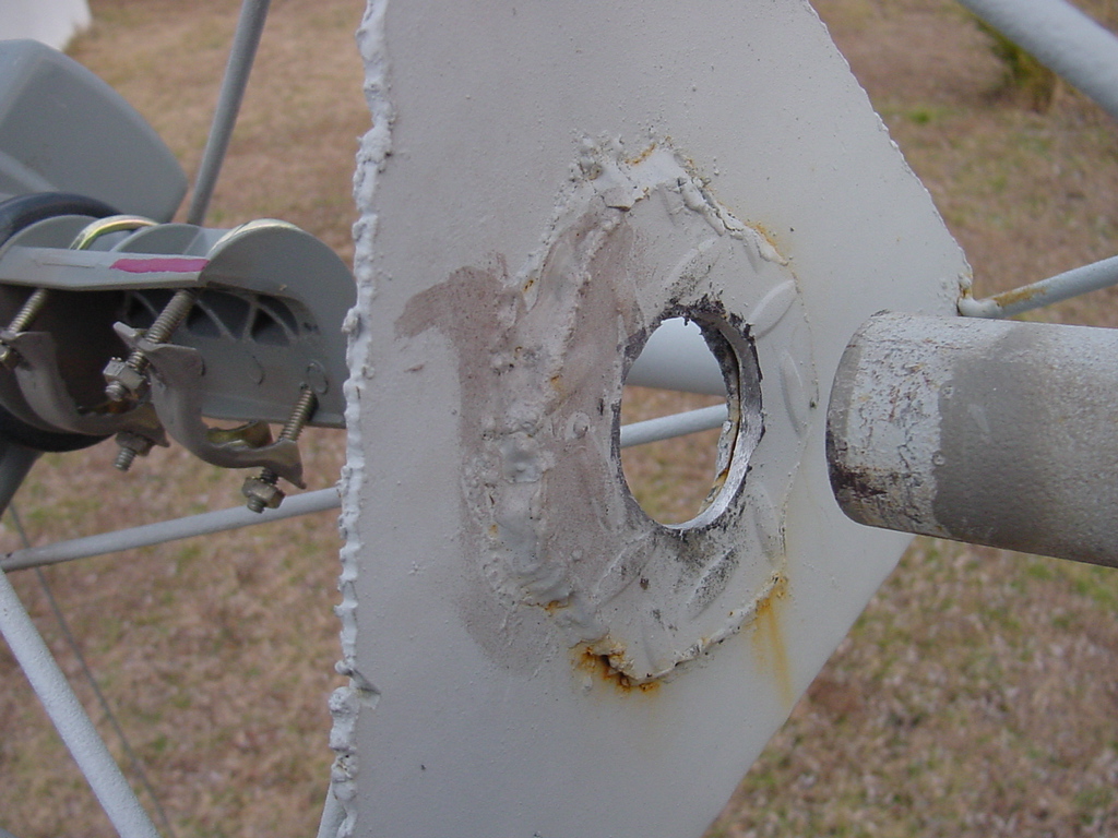
No Bearings
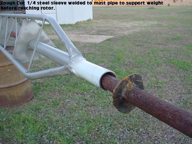
In place of costly bearings, I opted to try this method. This 1/4" steel sleeve welded to the mast pipe will support all the weight of the mast and antenna above the rotor. The tube you see will be filled with grease. The only drawback I see is the metal to metal where this sleeve contacts the top of the tower. I believe the weight above will not create too much resistance for the small rotor that I have. Also I'm considering adding an additional friction fit sleeve to the top of the tower to align the mast properly. Notice the cracks in the weld joints. These will be filled before final paint applied.

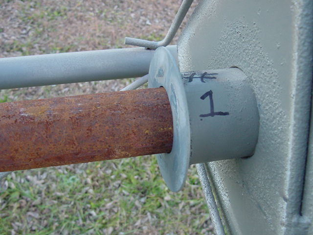
Closer view of top plate.
Yet Another.
Special attention was needed to align the friction fit holes for mast to go thru. Consider the top of tower to rotor for these alignments. Mast will be sanded and painted before antenna and coax attachment.

Getting Closer.
Breaker Breaker
All coax connection's will be sealed with a good commercial grade exterior electrical connection sealant.
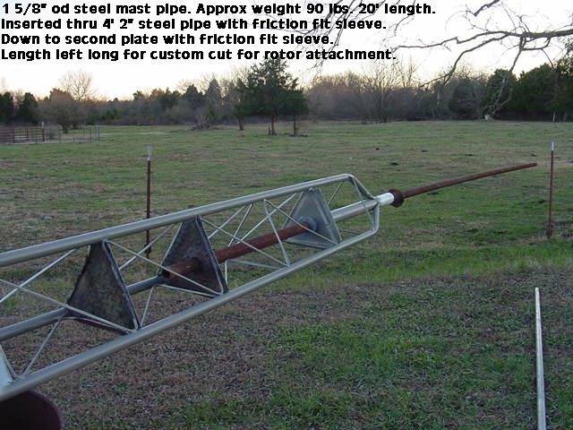
Its easy to see the weight of the mast pole here. I believe the additional weight will pay for itself here. The surface of this pipe is the same as some lighter grade and should not catch any more wind. So I'm going this route for the additional strength. This pipe was picked up at the local steel yard for salvage price. Approx. $15.00. With the top of the tower guyed off I will observe this installation for awhile. If observation shows mast to be too heavy I will change to a lighter weight first time down for maintenance.
Simple Tools
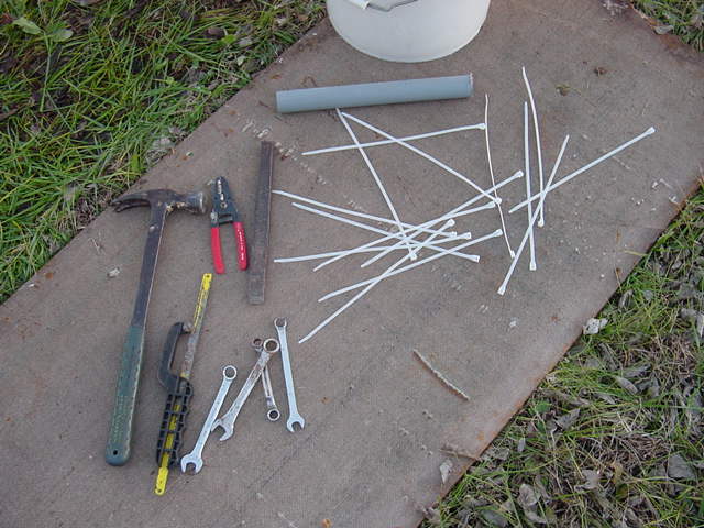
A few of the simple tools required to assemble tower to this point. Missing shovel and wheelbarrow. Whew!

Top of tower measurement where antenna mast inserts to tower is 47' 6"
Note: A curved steel sleeve should be installed in the bend of the guy wire here.
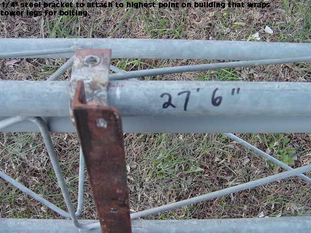
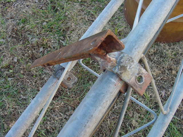
This 1/4" steel bracket attaches at the highest point on building and is the first supporting point eliminating guy wires close to ground. Bolts apply thru bracket around tower legs.
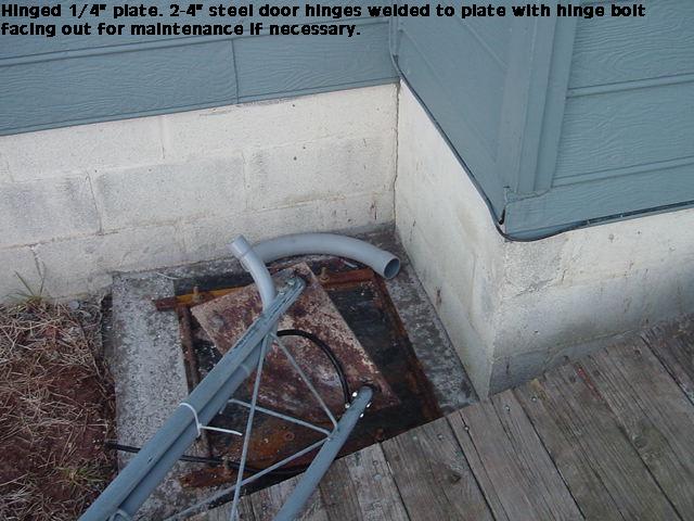

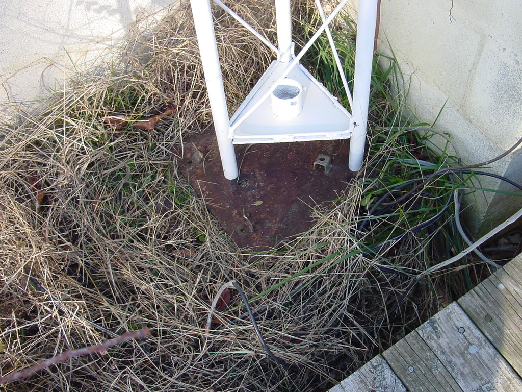
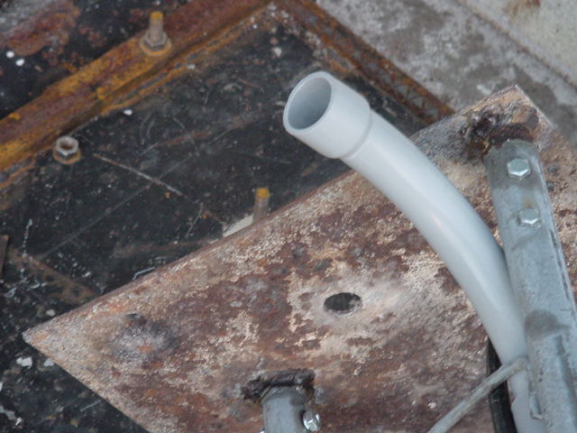
This is the folding hinged base plate, in the tower down position. This when raised will allow the 1/2" steel bolt thru the visible hole. A large heavy 1/4" steel homemade washer and nut will insure the tower's stability until upper brackets and guys can be attached.
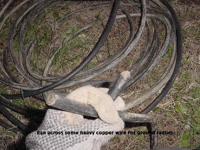
Grounding radials will be discussed later.

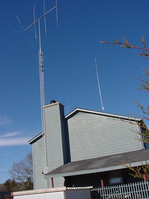
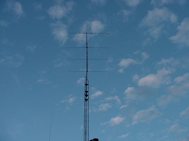
I'm installing a Moonraker 4 above this tower. I have been told the antenna should be at least two feet above the top of tower and guys, to help eliminate interference. The lower vertical elements of the antenna are about 9' The total antenna height will be approx. 60' 7" to antenna attachment point. The upper vertical elements will rise approx. 9' above this point.
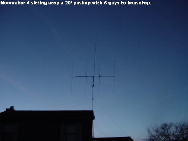
After my first Antron 99 lighting hit, I decided to go for my first set of beams. What a project. It took me 3 days to assemble and mount pole, antenna, and guys. I didn't have My Buddy to help. Enjoyed every minute of it. This view is after the first wind which was 70 m.p.h. on my handy 30' pushup pole. One guy wire broke in the first wind and allowed the top section of the pushup to buckle. No major damage. Just a couple bends in the lower vertical elements. Ole Rockytop was quick to come off the mountain to help re-erect the fallen antenna. After cutting off the top 10' section of the pushup Rockytop convinced me I had the Gamma Match turned the wrong way. So because of his many years experience and my no knowledge we took it apart and installed as he suggested. Upon research later that evening I discovered that he had in fact instructed me wrong. So I really got to know my new antenna soon. This installation has caught my eye every time the wind has blown. It has withstood several that I was really amazed that it could. I'm praying that this will last at least till I get this new tower erected.
I hope that this will help someone new in the radio business in their adventures and installations.
There's no way I could have made it without my trusted help.
My Buddy.
More to come!
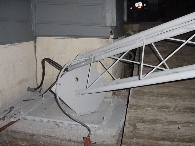
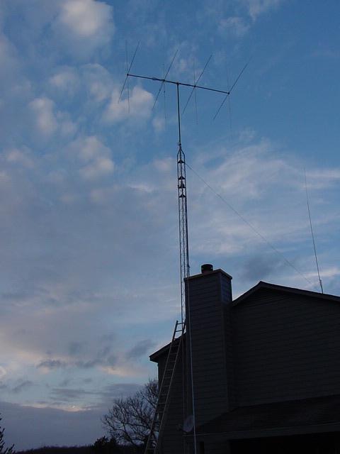
Okay here you see the tower on its way up. Its easy to see the hole in the base plate that folds over to meet the 1/2 steel bolt that allows immediate stability when you stand the tower up. Just put heavy washers and nut and it will hold the tower until you can anchor the guys and upper attachment points. Note how the ground wire in put out front to allow tower to be raised and lowered without disconnection. The 1 1/2" pvc is moveable and a short length of coax is left so to be protected at all times when tower is in use, but allows you to lower tower for maintenance.

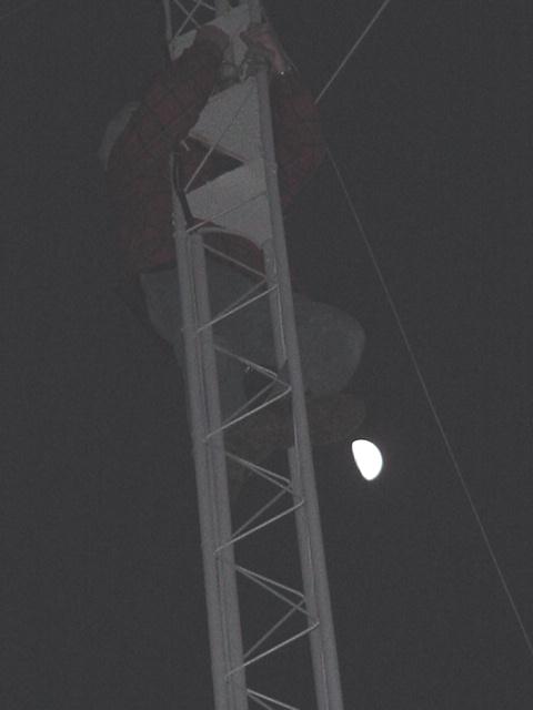
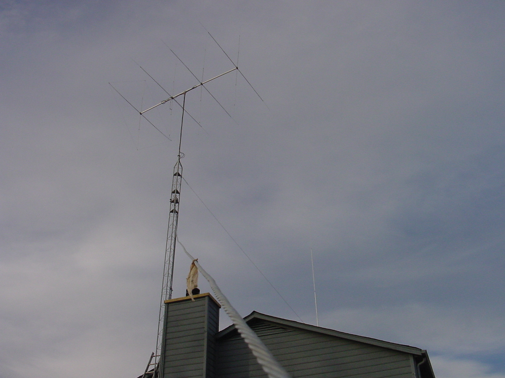
This photo shows a slight bend in the upper part of the tower. This is because I have a 100 lb. mast pole. Notice how the Moonraker 4 is turned for maintenance. The antenna should be turned for the best position before lowering tower.

As you can see, the hanging guy wire that is attached for hookup later. There will be two more when this project is complete. Also you can tell that the tower is not nearly as stressed as when all the weight of the mast and antenna were vertical.
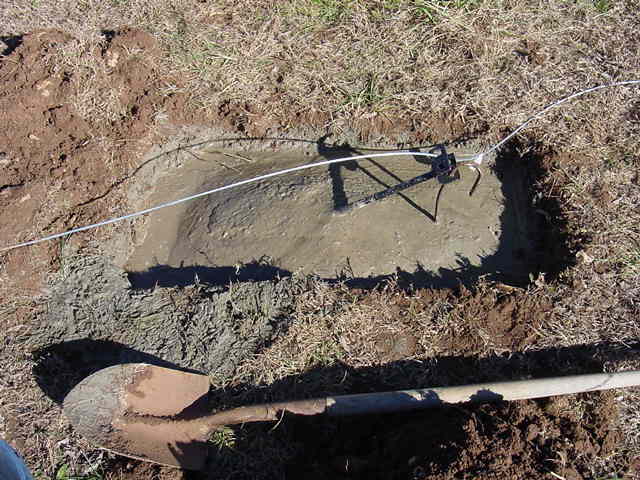
Approximately 3' x 2' x 1' concrete. I used a trailer screw down at an angle with a piece of 1/2" rebar driven with bend. The rebar is also in the concrete. Because of the depth of soil I was unable to put the anchors deep enough to suite me.
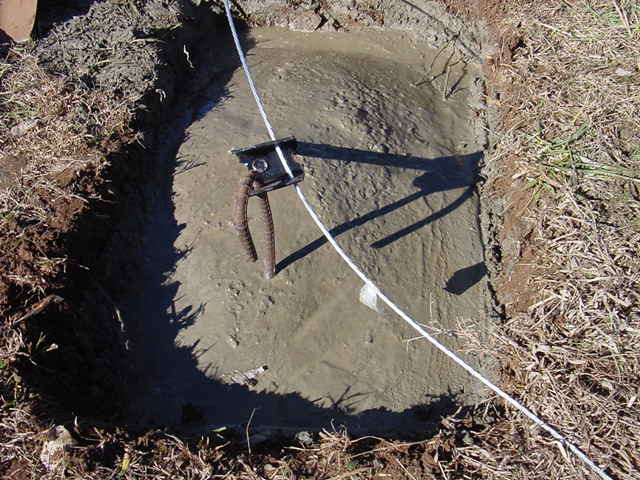
Another angle of last photo.
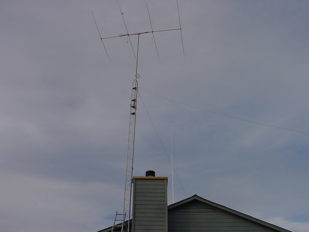
This is the first trip up with the Moonraker 4 on the tower. Tree was a little to close at dusk to prevent the mis-adjustments.
Boom is at 60'
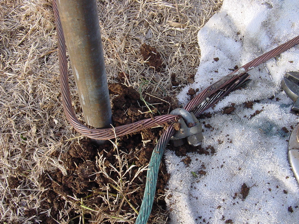
Okay this is the ground that goes to the top section of tower, A coupling from that point on carries a #4 solid copper wire to the mast of the antenna. Steel fence post used with 1/2" hole bored and wire twisted and then penetrated with bolt. Additional heavy copper wire added later to form triangle.
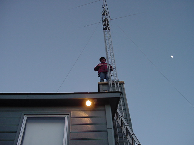
Man on top of chimney at the end of day placing anchor bolts at top.
Notice the guys are still loose.

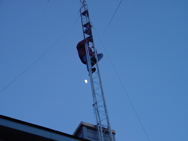
First time up Rohn Tower without guys installed. Hmmm??? Will this thing support me?
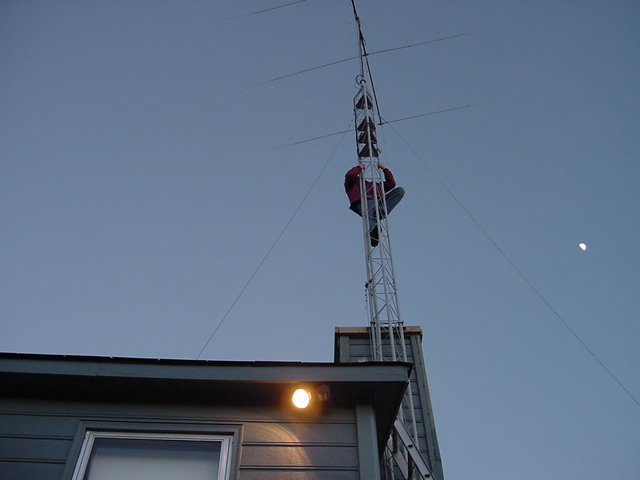
So Far So Good!
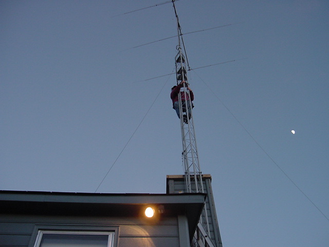
I'm Skeered!
Snap the picture quick. I'm coming down. Don't try this without the proper harness or belt.
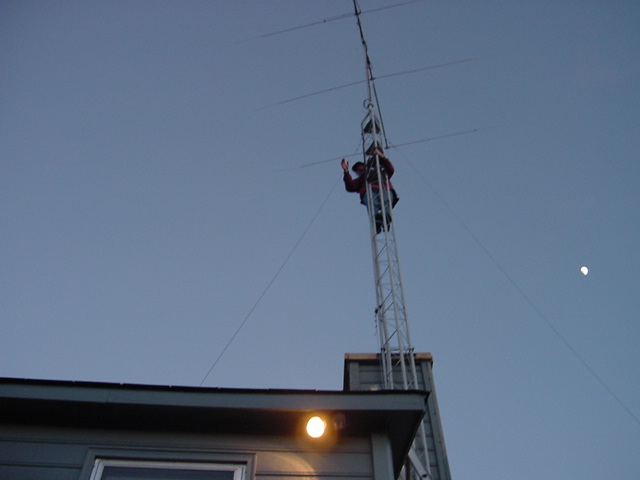
This angle looks as if tower is bending over. I hope its just the angle.
Did you ever freeze while upon a tower?

Dawn is Near!
Rotor work is suggested when the tower is laying over.
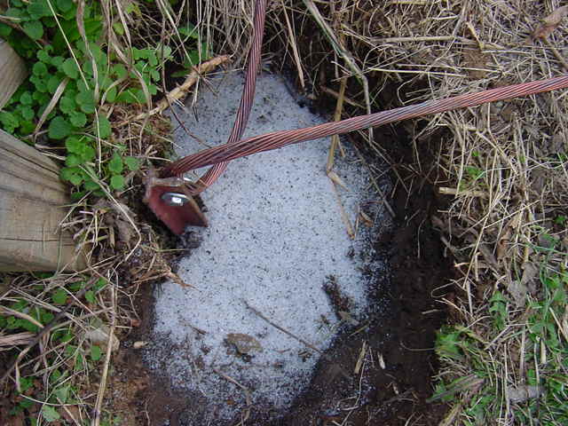
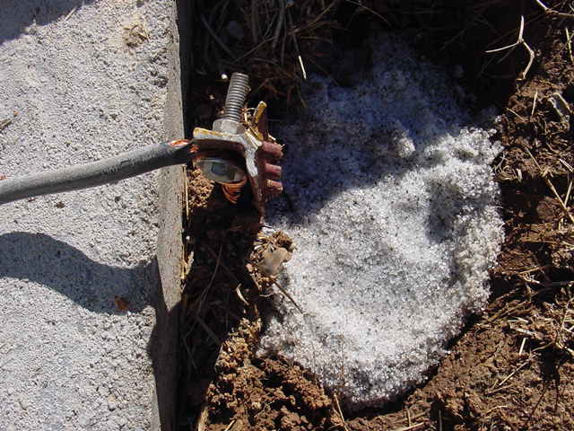
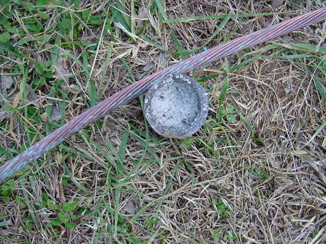
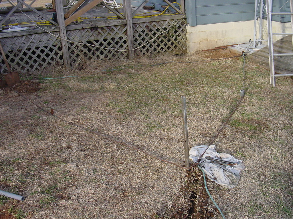
This is the first leg of a triangle. Again steel fence post as above with loop in copper headed for next post. Rock salt added for rocky soil. Water added a couple times before covering up.
Notice the boat crank on the deck rail above the yellow cord. This photo shows the triangle ground system. I added steel post in the middle of the runs. These are 1 1/2" steel. This allows me to add salt occasionally. There will be bolts added that attach the copper to these ground rods.
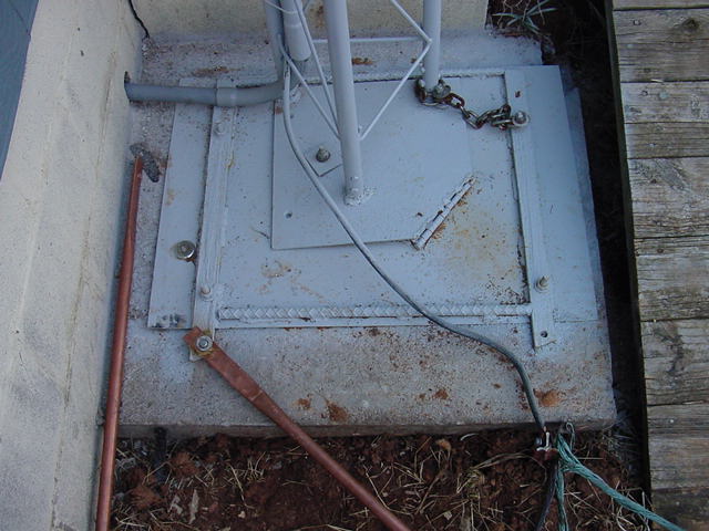
I added a heavy chain to help keep the tower from swinging when wind speed is up while lowering tower.
The tower base is bolted down, conduit in place. 3/4" copper water pipe flattened will be attached to the ground wire to better ground tower via base plate.
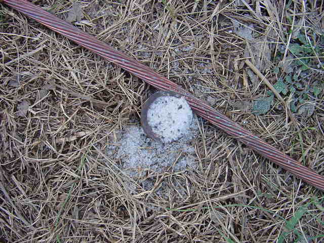
Rock salt added in steel pipe. This will continually allow salt to seep to base of pipe and help with rocky soil.
Again this copper wire will be bolted to steel pipe before burying wire. Salt will be added to the ditch wire will be buried in.
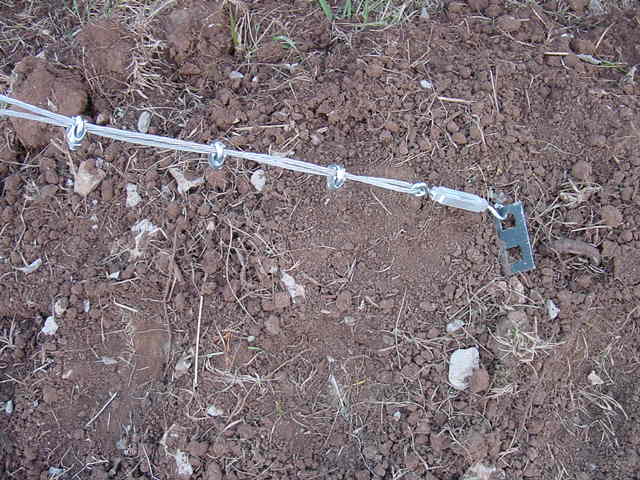
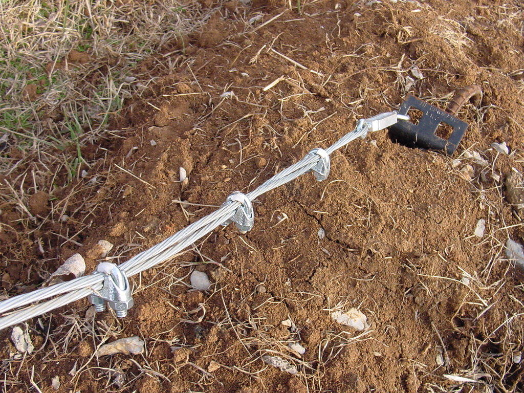
Guy wire attached with three clamps. Notice the rebar from photo above.
Adjustments made to antenna. Looks straight now.
Getting Closer.
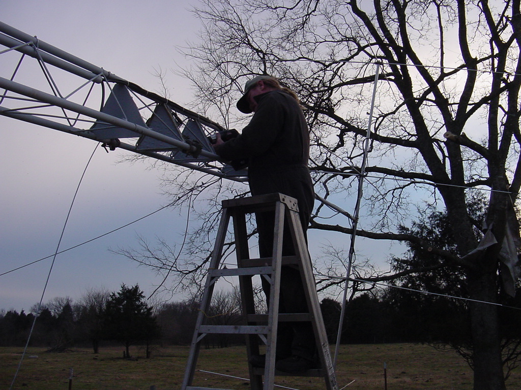
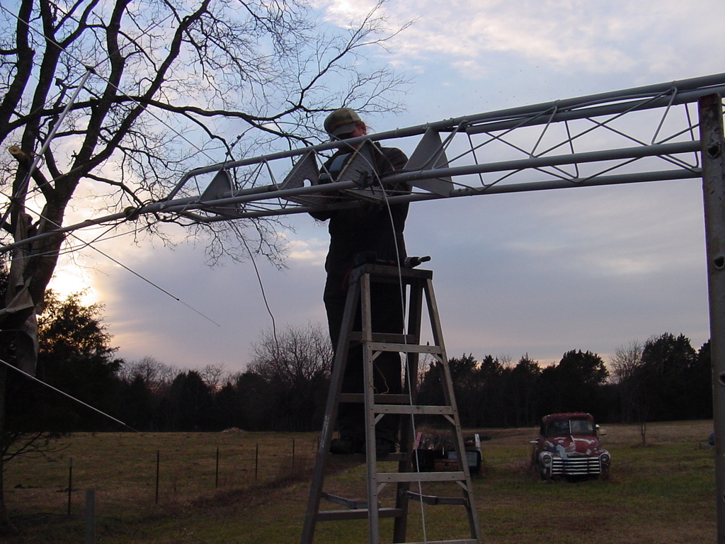
Man working on top 8' step ladder. Making adjustments with grinder. Holes were bored in top steel plate for guy wires to be inserted at three points. This allowed guys to be thru 1/4" steel and to wrap all three legs of tower. Conduit stops just below top section of tower. Notice the exposed coax on leg of tower with wire ties.
I had some complications with this friction fit part of tower. If I had it to do over again I would simple not have this plate at all. Alignment problems from above didn't allow the rotor to turn the mast pole 360' without making contact with sides. Several trips up the tower with a Dremel fixed this problem. After synchronizing the antenna and rotor I added red fingernail polish to rotor and to mast pole. This simplifies realignment in case maintenance requires removal. Believe it or not this is a $79.00 rotor from Radio Shack. So far so good. It worked well on a pushup I first had Moonraker 4 installed on. Can you tell this is my first tower now?
Heavy duty wire ties were used. PVC pipe cut in half and attached with silicone & wire ties to protect exposed coax from guy wire. Silicone should hold pvc in place if wire ties decompose.

My Buddy climbing ladder with instructions.
Man grinding out lower alignment problem. He thinks.
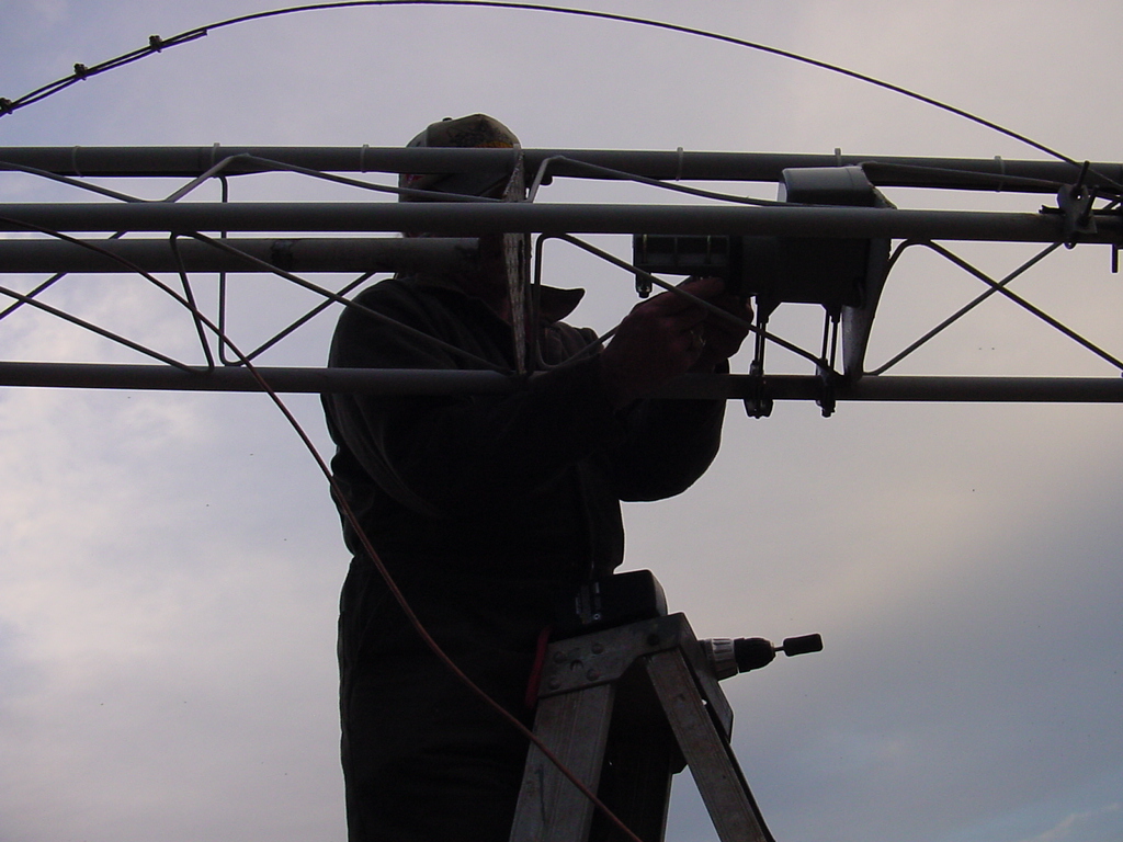
Big Job this thing is.
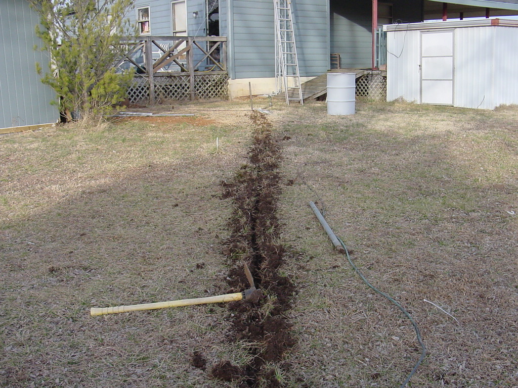
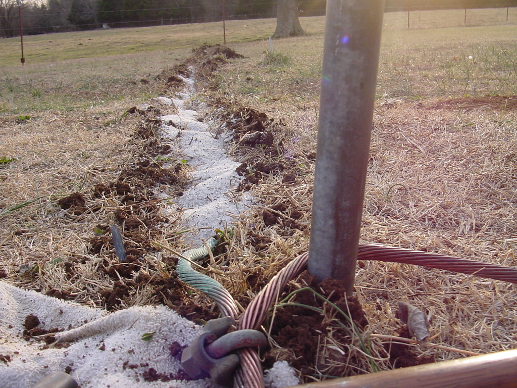
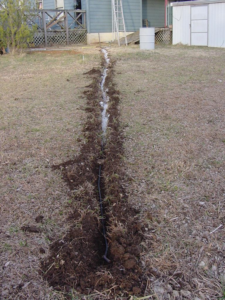
Notice the large ground rod where trench begins. This is the attachment point for the first radial ground. Trench is only a couple inches deep. Approximately 36' long.
Rough trench will be cleaned out and salt added before wire is inserted and covered up.
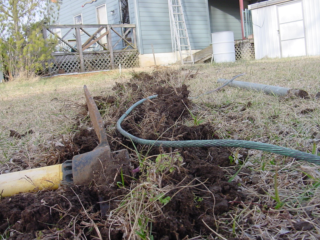
Copper ground radial connection with large clamps. Copper will be attached to ground rod with 1/2" bolt and washer before wire burial.
Another view of triangle.
Another view of guy connection.
3/16" steel guy from http://texastowers.com
Notice the slack in the wire. When the third guy is added the final adjustments will be made.
Notice right at the top of the tower, a loop has to be made in the coax so the antenna can turn without stretching the coax.

Copper wire laid in trench with salt visible. I cut some 12" steel wire to bend in half to push into ground to hold copper ground wire in place for salt and earth to be added.
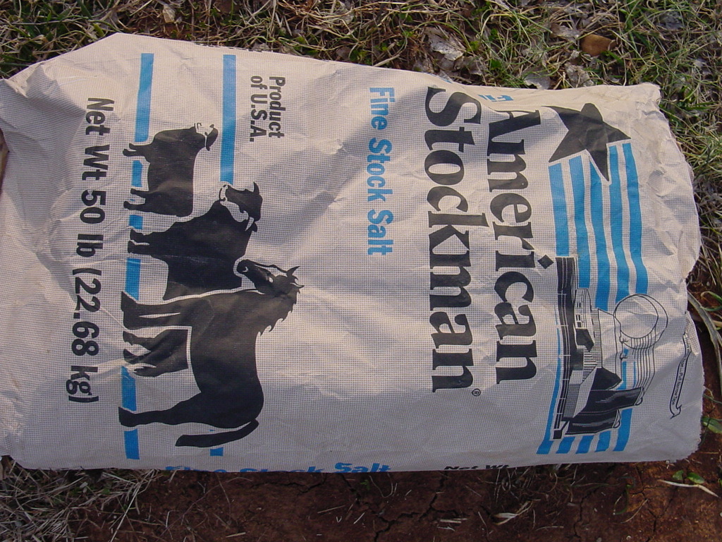
Picked up salt @ Tractor Supply
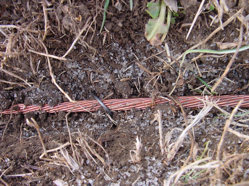
View of bent steel wire, (24" insulation support) cut in half. Again salt to be added before covering.

Yet another for those that don't yet have a clue..
Salt added and trench is not as crooked as salt makes it appear
Ground rod will be added at ends of radials.

10 gallons water added before covering trench up.
Another hard day. My Buddy
Revised
02/01/2004
02/17/2005
Click here for our Amazing E-Store.
Where you can find anything you might need at affordable prices!